ECG Biometrics System with Computer Mouse Device Type Electrodes
[Project Period] : DEC 2015 - JUL 2016
Authors
Junhyun Lee\(^1\) and Prof. Sang-Hoon Lee \(^{1,2}\)
\(^1\) Department of Biomedical Engineering, Korea University, Seoul, Republic of Korea
\(^2\) KU-KIST Graduate School of Converging Science and Technology, Korea University, Seoul, Republic of Korea
I conducted this personal project in 2016, while I was an undergraduate student researcher at the Intelligent Bio-MEMS Laboratory (iBML) at Korea University under the guidance of Professor Sanghoon Lee. In this lab, I participated in research on the fabrication of an elastic electrode material known as CNT/PDMS, a composite of carbon nanotube and poly-dimethylsiloxane. My goal was to apply this material in the field of medical instrumentation. However, due to time constraints, the integration of the CNT/PDMS electrodes with the biometrics system could not be achieved within the scope of this project. The primary stage's purpose was solely to establish the entire process for the ECG (Electrocardiogram, or EKG) biometrics system. Therefore, there is significant room for improvement in each component.
Abstract
In recent times, the electrocardiogram (ECG) has been instrumental not only in the diagnosis of cardiac conditions but also in the provision of individual access authorization. Yet, the application of ECG measurements often necessitates the use of specialized machines due to the essential components such as electrodes, amplifiers, filters, and a data acquisition module. The mandatory connection of electrodes to the individual's body and their subsequent wiring to the data acquisition machine often imposes mobility restrictions on the subject. As such, the practical integration of ECG-based biometrics into routine life has been a challenging endeavor.
In this study, we propose a novel, user-friendly device for ECG measurements that interfaces as a computer peripheral and incorporates built-in electrodes. Enabled by Bluetooth communication, this device could potentially facilitate the implementation of ECG biometrics into daily activities. For the categorization process, we employ the correlation coefficient and neural network methodologies.
1. Introduction
Biometric authentication has become a noteworthy method in modern security systems [1-5]. This study presents a novel, user-friendly device designed to leverage the advantages of electrocardiogram (ECG) measurements for biometric applications.
Various personal features, such as fingerprints, iris and retinal patterns, and vein structures, have been utilized in biometric systems [2]. However, each of these methods carries its inherent limitations. For instance, fingerprint recognition technology is susceptible to fingerprint theft, and scanners risk duplicating fingerprints left on the glass surface. Additionally, this method becomes ineffective if a fingerprint is significantly damaged or missing. Retinal scanning, while secure, can be inefficient for individuals with eye conditions such as blindness or cataracts. Furthermore, retinal scanners can be inconvenient to users due to the close contact required with the authentication terminal.
While the measurement of most biometric features demands expensive machinery, ECG can be captured using only a few chips and electrodes. Traditional ECG measurements, however, restrict user mobility due to wires and the use of leads I, II, III requiring at least four electrodes (left arm, left leg, right arm, right leg). This has rendered ECG signals somewhat cumbersome for biometric applications [6-9].
In this study, we have focused on using just lead I for biometric purposes [10-13], effectively reducing the number of necessary electrodes and wires. Our proposed system employs a mouse-type device with embedded electrodes for ECG measurement, a setup familiar to most people due to widespread use of computers and peripherals. This design can potentially increase user comfort during measurements. A previous study designed a keyboard-type electrode system for ECG measurements at the fingertip [11]. We posit, however, that a mouse-type electrode device can yield more stable signals due to the mouse case's ability to support the user's hand.
The ECG signal is measured using lead I electrodes and filtered using an analog filter. The filtered signal is then transmitted via Bluetooth communication and further processed by a digital filter. To mitigate baseline noise, we select 15 PQRST-waves to compute a mean wave. The measured signal is then compared to a database by calculating the correlation coefficient for classification. The user's identity is subsequently identified from the database entry with the highest correlation coefficient. Furthermore, we employ a basic neural network for improved categorization.
2. Methodology

Figure 1. block diagram of our ECG biometrics system.
The process utilized in our study is graphically represented in Figure 1 as a block diagram. This consists of two primary components: hardware and software. The left fingertip serves as the signal source, the right thumb acts as the reference source, and the right palm is used as a grounding point. ECG signal wave lead I can be obtained through measurements at these specific locations. The conditions for ECG acquisition are presented in Table 1.Table 1. ECG acquisition condition.
2-1. Hardware
The hardware component of our system is comprised of electrodes, a mouse body, wiring, circuits, and a Data Acquisition Module (DAQ) equipped with a Bluetooth communication chip.

Figure 2. Conceptual schematic of electrodes (left and center) and actual experimental setting (right)
Electrodes: As depicted in Figure 2 (left and center), the setup includes a yellow electrode for the left hand's finger and gray electrodes for the right hand's thumb and palm. The electrodes are fabricated from nickel tape with copper wire. Future works of this project may consider replacing the existing electrodes with a CNT/PDMS material.Circuit: The circuitry used incorporates a buffer, a differential amplifier, a secondary amplifier, and several filters. The designs shown in Figure 2, which include an integrated circuit inside the mouse body for signal processing, are proposals. The experimental circuit was assembled on an external breadboard. Future developments could replace this setup with an integrated circuit such as the ADS 1292.

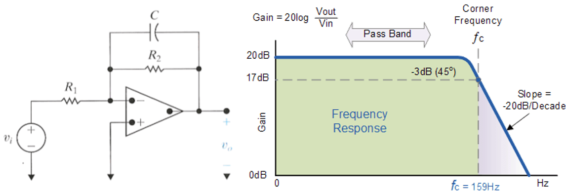
Figure 3. Buffer (1) and Differential Amplifier (2), image sourced from Wikipedia
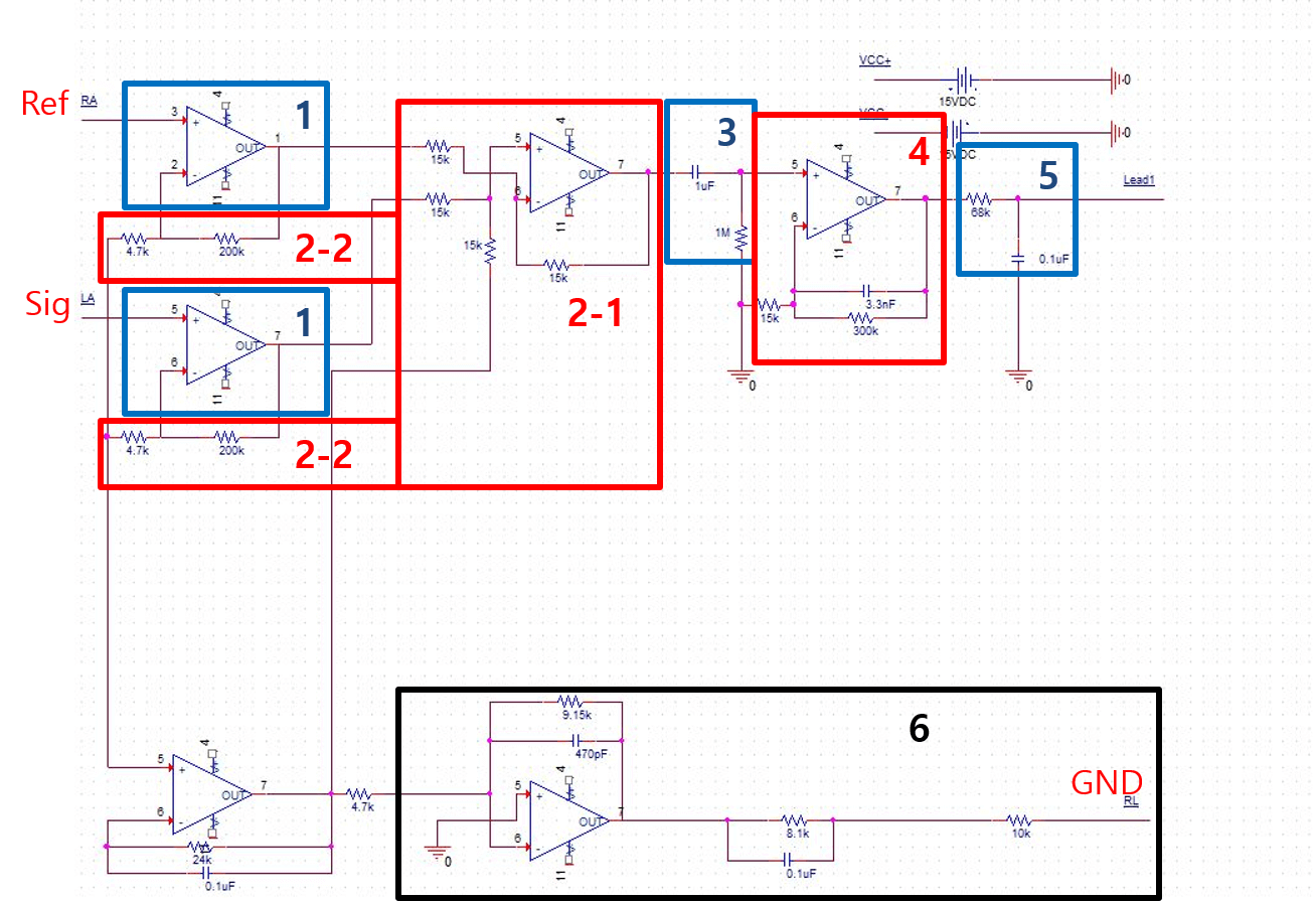
In Figure 6, the blue box labeled '1' indicates the buffer, which is used for high impedance. This allows us to obtain the signal in its entirety. Within the red box labeled '2-1', the differential amplifier has a gain of 1, due to the ratio of \(15 k\Omega : 15 k\Omega\). However, within the '2-2' region, resistors are marked as \(R_1\) and \(R_{gain}\). Here, we can achieve a gain of \(1+ \frac{200k}{4.7k} = 43.55\). The combination of the buffer (blue box 1) and the differential amplifier (red box 2) is known as the implementation circuit. This could be replaced in future iterations with an integrated circuit such as the INA 118.
Figure 4. High Pass Filter, image sourced from Wikipedia
The blue box labeled '3' in Figure 6 houses the high pass filter. This filter has a cutoff frequency of \(\frac{1}{2 \times \pi \times R \times C} = \frac{1}{2 \times \pi \times 10^6 \times 10^{-6}} = \frac{1}{2 \times \pi}\), or about 0.16Hz. Despite its narrow cutoff bandwidth, this filter plays a crucial role. It eliminates the DC component, allowing any saturated signal to return to a stable state.
Figure 5. Active Low Pass Filter, image sourced from Wikipedia
The red box labeled '4' in Figure 6 illustrates the active low pass filter and secondary amplifier, which amplify the signal. Its gain is calculated as \(1 + \frac{300}{15} = 21\). Lastly, the black box labeled '6' depicts the use of a driven right leg (DRL) circuit to eliminate common voltage using negative feedback. This enhances the Common-Mode Rejection Ratio (CMRR) and reduces 60Hz noise.
Figure 6. Schematic of our signal filter circuit
Data Acquisition Module: An Arduino UNO functions as the DAQ in this system. The DAQ comprises analog-to-digital converters (ADC) and a Bluetooth module (HC-06, China). Future improvements could substitute this DAQ with an integrated DAQ chip like the ADuCM360. There are existing all-in-one solution chips for the hardware component (excluding electrodes), such as the S3FBP5A Samsung bio processor. These could potentially be utilized in future works of this project.2-2. Software
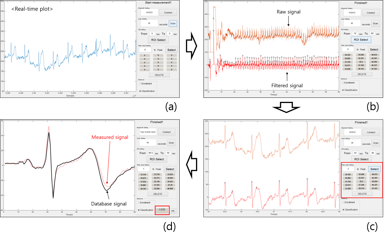
The data acquisition and all digital processes are managed by a MATLAB graphical user interface (GUI), as shown in Figure 7. Initially, the name of the Bluetooth module is input, and the connect button is pressed. Once the module is connected, the subject's hand is placed on the electrodes. Subjects are notified about the purpose of the experiment and the study. Upon clicking the scan button, the ECG measurement commences.
Once the scan is complete, two lines appear in the axes, as illustrated in Figure 7 (b). The upper line represents the raw signal, which has only been filtered by the analog filter. The second line is the signal after digital filtering. Peaks in the signal are detected using the MATLAB 'findpeaks' function. The region of interest (ROI) is then set, and the scale of the axes is adjusted based on the ROI. Fifteen R-peaks are then manually selected. Future work could automate this process using deep learning techniques for object detection or segmentation.
The selected ECG pulses are then summed and processed based on the chosen final behavior (enrollment or classification). For classification, the measured ECG data is compared with database signals by calculating correlation coefficients.

Figure 7. MATLAB GUI for biometrics
The use of correlation methods, however, does have its limitations. If there are numerous subjects, the error rate is likely to increase. This is due to the correlation value's inability to capture the complex information or patterns within ECG signals. Therefore, a more precise method for classification, such as artificial neural networks, is needed. We used a simple neural network known as a multilayer perceptron, as depicted in Figure 8. Future iterations of this project might replace the multilayer perceptron with a convolutional neural network and modify the input signals, such as the power spectrum.
Figure 8. Structure of multilayer perceptron
For the input, signals were segmented by heartbeat, as shown in Figure 9. This approach yielded 125 signals from seven subjects. Out of these, 100 signals were used as the training set and the remaining 25 signals constituted the test set.
Figure 9. ECG signals for multilayer perceptron input
Results
The ECG signal is initially filtered through an analog filter with a passband frequency range of 0.72 Hz to 59.54 Hz. The primarily filtered signal is obtained through the Bluetooth module. In the software component, the primary signal is depicted as the upper signal in Figure 7 (b).
A second filtration process is needed to set the signal baseline, requiring the use of a digital filter within the frequency band of 1.5 Hz to 58 Hz. This filtered signal is represented as the lower signal in Figure 7 (b). Peak points in the signal are identified using the MATLAB function 'findpeaks', with the standard setting for peak detection set as 'MinPeakProminence'. As individual peak values and wave shapes differ significantly, the setting value cannot be uniformly applied, necessitating manual peak selection via the software GUI. To reduce base noise, the average signal of the selected peaks is calculated.
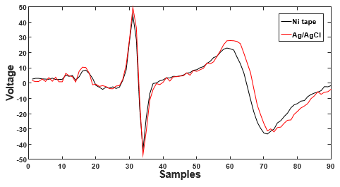
Figure 10 displays a comparison between the database signal recorded using our electrodes and a signal measured using commercial Ag/AgCl electrodes (Covidien, Canada) to validate our electrode design. The calculated correlation coefficient is 0.9565.

Figure 10. ECG signal measured on the Ni tape and the Ag/AgCl electrodes
As illustrated in Figure 7, the GUI presents two radio buttons for final behaviors: enrollment and classification. If a user's ECG signal is not in the database, the 'enrollment' option should be selected, at which point the user's name is linked with the measured ECG signal in the database. For classification, the 'classification' button is selected. Figure 7 (d) displays the final state of the GUI for classification, where the red line represents the measured signal and the black line represents a database signal from a few days prior. Classification results are displayed in the red box in Figure 7 (d), with the correct result shown. In addition to the methods mentioned above, we also conducted an experiment using a neural network for classification. The results are shown in Figure 11. Of the total 125 signals from seven subjects, 100 signals were utilized as the training set, while the remaining 25 were used as the test set. Both training and test sets yielded a 100% accuracy rate. However, given the size of the dataset, this result does not imply model perfection, but merely demonstrates feasibility.
Figure 11. The result of classification on multilayer perceptron.
In this study, we also propose the use of a dry and flexible type of electrode. Hence, we fabricated electrodes using carbon nanotubes (CNT) with polydimethylsiloxane (PDMS). Given its physical properties, it can be adhered to a mouse. To minimize contact resistance, copper wire was inserted into the CNT/PDMS. PDMS lends durability to the electrode. The CNT/PDMS is depicted in Figure 12.
Figure 12. CNT/PDMS electrodes.
Conclusion
In this study, we have developed a prototype for a biometric system, and introduced mouse-type electrodes for ECG-based biometrics. Given people's familiarity with computers and peripheral devices, this represents a user-friendly approach to biometrics. In a different study, keyboard-type electrodes were designed for ECG measurement at the fingertip, without the need for a mouse. However, we believe that a mouse-type electrode can provide more stable signals as the mouse casing provides support for the user's hand. Furthermore, data transmission is accomplished through Bluetooth communication.
As observed in Figure 9, ECG signals from different subjects are distinct, making it possible to identify users enrolled in the database by comparing correlation coefficients. Our work employs a dry-type electrode, since a wet-type electrode would be unsuitable for everyday devices such as keyboards and mice. The electrodes proposed in our study are fabricated from nickel tape. When comparing these proposed electrodes to commercial electrodes, the differences are insignificant, as shown in Figure 10, with a correlation coefficient of 0.9565. This correlation is substantial enough to regard the signal as reliable for biometric purposes. Hence, based on this data, the proposed electrodes' classifications gain credibility and may find real-life application in ECG biometrics.
Nevertheless, there are challenges addressed in this paper. Firstly, the comparison of correlation coefficients may not be the perfect evaluation method. In order to reject noise, we have applied filters and summation to the measured signal. Consequently, the signal is modified, and detailed features are eliminated along with the noise. To circumvent this issue, wavelet transform is suggested [17-19]. Employing wavelet transform could enable detailed feature extraction and automated classification. For classification with detailed features, the support vector machine classifier is often employed [11, 20-22], but in our case, we used a simple neural network, a multilayer perceptron.
The second challenge pertains to electrode oxidation. Due to the impracticality of wet-type electrodes for everyday use, we fabricated the electrodes with Ni tape in this study [23]. However, metals are prone to oxidation, which can generate noise, leading to errors in classification. This issue could potentially be mitigated by using polymer-type electrodes, such as those made of carbon nanotube with polydimethylsiloxane (CNT/PDMS) [24].
References
- Silva H, Lourenço A, Canento F, Fred AL, Raposo N, editors. ECG Biometrics: Principles and Applications. BIOSIGNALS; 2013.
- Jain AK, Ross A, Prabhakar S. An introduction to biometric recognition. Circuits and Systems for Video Technology, IEEE Transactions on. 2004;14(1):4-20.
- Jain A, Bolle R, Pankanti S. Biometrics: personal identification in networked society: Springer Science & Business Media; 2006.
- Jain AK, Ross A, Pankanti S. Biometrics: a tool for information security. Information Forensics and Security, IEEE Transactions on. 2006;1(2):125-43.
- Wayman J, Jain A, Maltoni D, Maio D. An introduction to biometric authentication systems: Springer; 2005.
- Han Y-H. A Study on Monitoring of Bio-Signal for u-Health System. Journal of the Korea society of computer and information. 2011;16(3):9-15.
- Chung W-Y, Lee Y-D, Jung S-J, editors. A wireless sensor network compatible wearable u-healthcare monitoring system using integrated ECG, accelerometer and SpO 2. Engineering in Medicine and Biology Society, 2008 EMBS 2008 30th Annual International Conference of the IEEE; 2008: IEEE.
- Muhlsteff J, Such O, Schmidt R, Perkuhn M, Reiter H, Lauter J, et al., editors. Wearable approach for continuous ECG-and activity patient-monitoring. Engineering in Medicine and Biology Society, 2004 IEMBS'04 26th Annual International Conference of the IEEE; 2004: IEEE.
- Led S, Fernández J, Serrano L, editors. Design of a wearable device for ECG continuous monitoring using wireless technology. Engineering in Medicine and Biology Society, 2004 IEMBS'04 26th Annual International Conference of the IEEE; 2004: IEEE.
- Silva H, Gamboa H, Fred A. One lead ECG based personal identification with feature subspace ensembles. Machine Learning and Data Mining in Pattern Recognition: Springer; 2007. p. 770-83.
- Da Silva HP, Fred A, Lourenco A, Jain AK, editors. Finger ECG signal for user authentication: usability and performance. Biometrics: Theory, Applications and Systems (BTAS), 2013 IEEE Sixth International Conference on; 2013: IEEE.
- Shen T-W, Tompkins W, Hu Y, editors. One-lead ECG for identity verification. Engineering in Medicine and Biology, 2002 24th Annual Conference and the Annual Fall Meeting of the Biomedical Engineering Society EMBS/BMES Conference, 2002 Proceedings of the Second Joint; 2002: IEEE.
- Shen T-W, Tompkins WJ, Hu YH. Implementation of a one-lead ECG human identification system on a normal population. Journal of Engineering and Computer Innovations. 2011;2(1):12-21.
- Aihua F, Chunhua B, Xinbao N, Aijun H, Jianjun Z, editors. Portable electrocardiogram monitor based on ARM. 2008 International Conference on Information Technology and Applications in Biomedicine; 2008.
- Ng KA, Chan PK. A CMOS analog front-end IC for portable EEG/ECG monitoring applications. Circuits and Systems I: Regular Papers, IEEE Transactions on. 2005;52(11):2335-47.
- Agarwal R, Sonkusale S, editors. Direct Analog-to-QRS detection front-end architecture for wearable ECG applications. Engineering in Medicine and Biology Society (EMBC), 2010 Annual International Conference of the IEEE; 2010: IEEE.
- Li C, Zheng C, Tai C. Detection of ECG characteristic points using wavelet transforms. Biomedical Engineering, IEEE Transactions on. 1995;42(1):21-8.
- Sahambi J, Tandon S, Bhatt R. Using wavelet transforms for ECG characterization. An on-line digital signal processing system. Engineering in Medicine and Biology Magazine, IEEE. 1997;16(1):77-83.
- Bahoura M, Hassani M, Hubin M. DSP implementation of wavelet transform for real time ECG wave forms detection and heart rate analysis. Computer methods and programs in biomedicine. 1997;52(1):35-44.
- Odinaka I, Lai P-H, Kaplan AD, O'Sullivan JA, Sirevaag EJ, Rohrbaugh JW. ECG biometric recognition: A comparative analysis. Information Forensics and Security, IEEE Transactions on. 2012;7(6):1812-24.
- Raj PS. ECG Biometrics using Intuitive Bases and Support Vector Machines: University of Toronto; 2014.
- Lourenço A, Silva H, Fred A, editors. ECG-based biometrics: A real time classification approach. Machine Learning for Signal Processing (MLSP), 2012 IEEE International Workshop on; 2012: IEEE.
- Gruetzmann A, Hansen S, Müller J. Novel dry electrodes for ECG monitoring. Physiological measurement. 2007;28(11):1375.
- Jung H-C, Moon J-H, Baek D-H, Lee J-H, Choi Y-Y, Hong J-S, et al. CNT/PDMS composite flexible dry electrodesfor long-term ECG monitoring. Biomedical Engineering, IEEE Transactions on. 2012;59(5):1472-9.